
Scroll down to see all the illustrations on the page


Pages


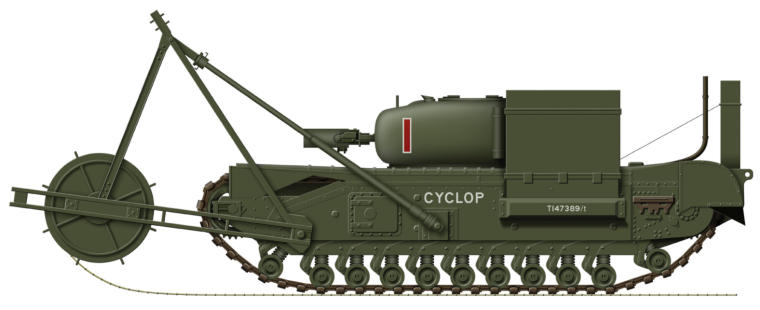
Churchill AVRE Mat Layer
The Churchill AVRE came about after the lessons of the Dieppe
Raid in August 1942 on the French coast had been learnt. They
were designed to be used by the Royal Engineers of Assault
Battalions in overcoming beach obstacles and fortifications,
and were first used on a large scale during the Normandy
landings in June 1944, where they proved to be very effective
in demolishing structures such as pillboxes, bunkers and
buildings. Many others were also adapted to carry all manner
of special equipment. The Mat Layer was a Churchill AVRE fitted
with a large bobbin at the front, and as the tank went up the
S P E C I F I C A T I O N :
Vehicle Weight: 38.5 tons
Dimensions: Length 24 ft 5 ins, Width 8 ft, Height 8 ft 2 ins
Powerplant: 1 x Bedford 350 hp petrol engine
Performance: Maximum speed 12½ mph, Range 90 miles
Armament: 1 x 290 mm Spigot Mortar, 1 x 7.62 mm machine gun
Armour: Maximum thickness 102 mm
Crew: 4
beach a reinforced canvas mat was unrolled, which provided a
good surface for vehicles to travel over. Once unrolled the
equipment could then be discarded and the tank could then be
operate as a normal AVRE. Another version was fitted to carry
fascines. These had been used in World War One, and were
bundles of wooden poles or brushwood that could be released
to fill a ditch or form a step to overcome beach obstacles. The
Churchill AVRE remained in service with the British Army until
the mid 1950s when they were replaced by versions using the
Centurion Tank, and today by the Challenger II.
Country of Origin: UK
Number Built: 754
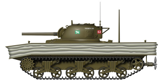
Valentine Bridge Layer
During the early part of World War Two the Scissor Bridge No 1
was developed by the Experimental Bridging Establishment
and a prototype built on the chassis of a light tank. The bridge
itself was carried folded in two on top of the tank with a large
hinge joining the two halves. The bridge had a maximum
tracked load of 24 tons (Class 24), and when deployed could
span a 30 ft gap. The mechanism that unfolded the bridge was
a long threaded screw inside a tube which was driven from the
engine, the launching cycle taking just 2½ minutes. The design
was accepted for production and initially the bridge vehicle was
S P E C I F I C A T I O N :
Vehicle Weight: 19.6 tons
Dimensions: Length 23 ft 7 ins, Width 9 ft 6 ins, height 11 ft 3 ins
Powerplant: 1 x AEC 131 hp diesel engine
Performance: Maximum speed 15 mph, Range 90 miles
Armour: Maximum thickness 65 mm • Crew: 2/3
Scissor Bridge No 1: Maximum obstacle span:30 ft,
Maximum load 30 tons, Deployment time 1½ minutes
the Covenantor tank, but after about 80 had been converted
the equipment was upgraded to Class 30 (30 tons) and all
further vehicles used the Valentine tank. Conversions of the
Valentine tank were carried out at the Southern Railway's
Eastleigh Works in Hampshire, and involved removing the
turret which were then used on the AEC Mark I armoured cars.
Six bridgelayers were issued to each armoured brigade that
were equipped with cruiser or medium tanks, and were
deployed in the Italy, North-Western Europe and in Burma by
British and Commonwealth forces.
Country of Origin: UK
Number Built: 192
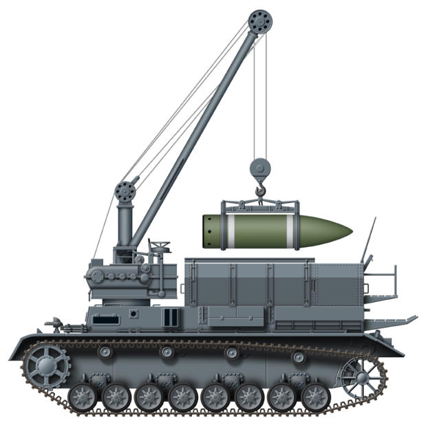
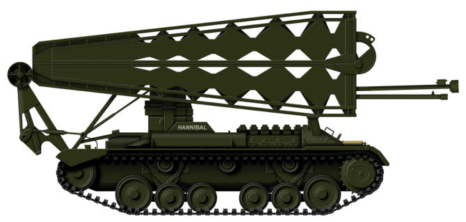
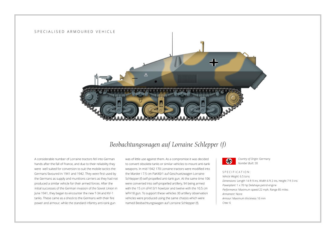
Panzer IV Munitionsschlepper
In March 1936 Rheinmetall made a proposal for a super
heavy howitzer to attack the Maginot Line. The design they
decided on was a self-propelled weapon, and during 1938-
39 extensive trials took place to investigate the ground
pressure and steering of such an enormous vehicle. Firing
trials of the 60 cm mortar took place in 1930 with trials of
the prototype being carried out in May 1940. Known as the
Karl-Gerät Mörser seven were built, and to support these
with ammunition a vehicle was required that could cope
with the heavy shells, the largest being the heavy concrete
piercing shell which weighed over 2 tons each. The vehicle
chosen for modification was the Panzer IV, and a design
was prepared for the purpose. The turret was removed
and the superstructure remodelled so they could carry
four 3,700 lb shells, while a 3.5 ton crane was installed to
load and transfer the ammunition. Depending on their
mission, each Karl required two or three of these support
vehicles to carry their applicable heavy munitions. The
Karls were mainly deployed on the Eastern Front, most
notably during the siege of Sevastopol in 1942 and the
Warsaw uprising in 1944.
S P E C I F I C A T I O N :
Vehicle Weight: 25 tons
Dimensions: Length 18 ft 5 ins, Width 9 ft 6 ins, Height 8 ft 8 ins
Powerplant: 1 x Maybach 300 hp petrol engine
Performance: Maximum speed 19 mph, Range 93 miles
Armament: None
Armour: Maximum thickness 15 mm
Crew: 4
Country of Origin: Germany
Number Built: 21
A27L Centaur Dozer
In 1942 fears that there would be a shortage of the newly
developed Rolls-Royce Meteor engine for the new A27 Cruiser
Tank led to 1,000 tanks being powered by the Nuffield 395 hp
Liberty engine, and to distinguish the two types the Meteor
engined tanks became the A27(M) Cromwell, and those with
the Liberty engine the A27(L) Centaur. The first Centaur was
competed in July 1942, but trials showed that the overworked
Liberty engine had an even shorter lifespan and was even less
reliable than it had been in the Crusader. Several attempts
were made to solve the problems, but the real problem was
S P E C I F I C A T I O N :
Vehicle Weight: 19.5 tons
Dimensions: Length 20 ft 10 ins, Width 9 ft, Height 9 ft 4 ins
Powerplant: 1 x Nuffield 395 hp Liberty petrol engine
Performance: Maximum speed 26 mph, Range 164 miles
Armament: 1 x 7.92 mm Besa machine guns
Armour: Maximum thickness 76 mm
Crew: 2
that the Liberty wasn't powerful enough for the weight of the
tank which put an enormous strain on the engine. Despite this
large scale production of the tank went ahead, although most
were used for training or later re-engined with the Meteor and
became Cromwells. A small number of Centaurs however were
used in action. About 80 were rearmed with a 95 mm howitzer
which were used on D-Day by the Royal Marines to provide fire
support for the Commandos. Other specialised conversions of
the Centaur included an armoured bulldozer, an armoured
recovery vehicle and an observation post.
Country of Origin: UK
Number Produced: Unknown
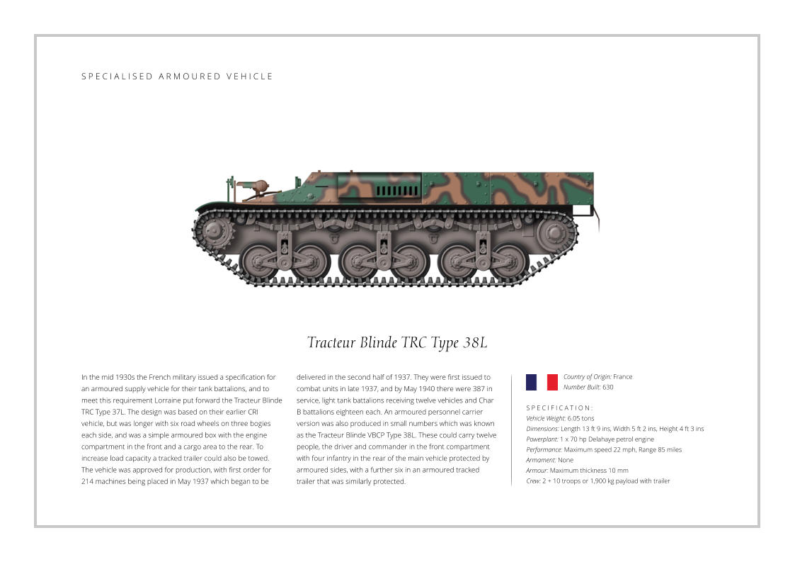
S P E C I A L I S E D A R M O U R E D V E H I C L E
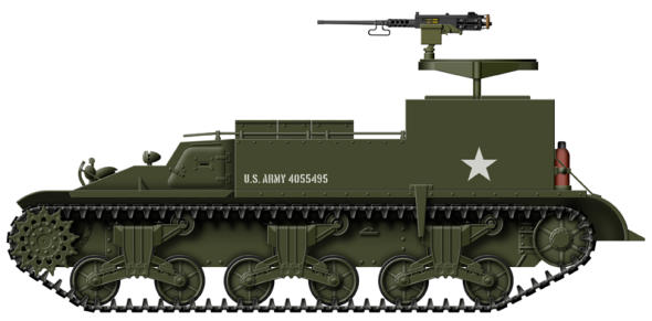
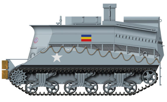
M30 Cargo Carrier
Limited space aboard the M12 Gun Motor Carriage meant that
only 10 shells and propellant could be carried, and to alleviate
the situation a support vehicle was produced. This was known
as the M30 Cargo Carrier which was specifically designed to
support the M12, and in service they would operate in tandem.
The M30 was a modified M12 designed to carry the main part
of the gun crew and an additional 40 rounds of ammunition
and other supplies. For defence they were armed with a 0.50
inch Browning machine gun on a ring mount. The final M12
was completed in March 1943, but the Artillery Branch showed
S P E C I F I C A T I O N :
Vehicle Weight: 20.67 tons
Dimensions: Length 22 ft 1 ins, Width 8 ft 10 ins, Height 7 ft 3 ins
Powerplant: 1 x 420 hp Continental petrol engine
Performance: Maximum speed 21 mph, Range 86 miles
Armament: 1 x 0.5 inch Browning machine gun
Armour: Maximum 51 mm
Crew: 2 + 6 gun crew
little interest in the M12, and for most of 1943 they were either
mothballed or used in training. This thinking however changed
for the planned invasion of Europe, where M12s and M30s
were deployed throughout the campaign after the D-Day
landings in North-West Europe until the end of the war.
Production of the M12 only amounted to 100 vehicles and a
corresponding number of M30s but after the end of the war in
Europe the M12 was declared obsolete and replaced in service
by the M40 155 Gun Motor Carriage, the M12s being scrapped
alongside the M30 Cargo Carriers.
Country of Origin: USA
Number Built: 100
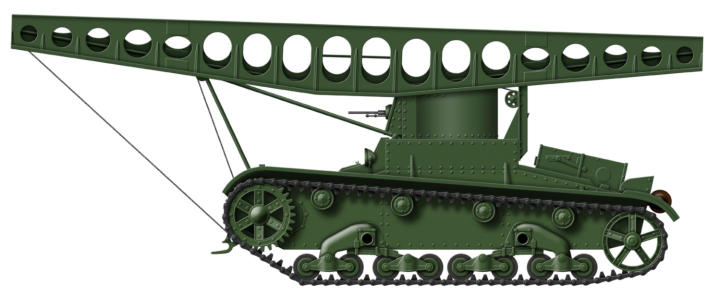
ST-26 Bridge Laying Tank
The ST-26 Bridge Laying tank was based on the twin turreted
T-26 model 1931 chassis. The ST-26 had only one shortened
turret which was located in the middle of the hull which was
armed with a DT 7.62 mm machine gun. The bridge was metal
tracked and just over 24 ft (7.35 m) long and weighed just over
1 ton (2,400 lbs). The supports for the bridge consisted of a
front frame with two forks and two guiding rollers, lower forks
with a hoisting mechanism and a roller, a rear frame with
mounts and two rollers, and a cable winch which was located
inside the vehicle. The ST-26 bridge was capable of crossing
S P E C I F I C A T I O N :
Vehicle Weight: 9 tons
Dimensions: Length 15 ft 3 ins, Width 8 ft, Height 7 ft 4 ins
Powerplant: 1 x 90 hp GAZ petrol engine
Performance: Maximum speed 18 mph, Range 124 miles
Armament: 1 x 7.62 mm machine guns
Armour: Maximum thickness 15 mm
Crew: 3
trenches and streams up to 20ft (6 m) wide and barriers up
to 6 ft (2 m) high, and had a maximum load rating of 14 tons
which was capable of supporting the T-26 and BT series of
tanks. The bridge could be laid with the help of the cable winch
in 30 - 40 seconds which did not require the crew to exit the
vehicle, while raising the bridge took 2 - 3 minutes did require
the commander to come out of the vehicle in order to oversee
the operation. The ST-26 with its cable system was trialled in
the summer of 1932 and accepted for service, and in total
around 70 were built.
Country of Origin: USSR
Number Built: 70+
S P E C I A L I S E D A R M O U R E D V E H I C L E
S P E C I A L I S E D A R M O U R E D V E H I C L E

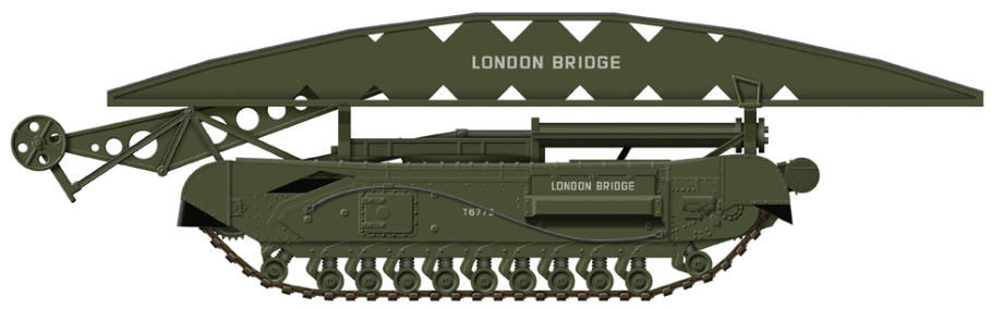
Churchill Bridge Layer
The British had already experimented with bridge laying tanks
shortly after the start of World War Two, with the Valentine and
Covenanter being produced with the Scissors Bridge No 1. In
1942 work began on another major system which was the Tank
Bridge No 2 for heavier loads, and was a Class 60 for tracked
loads (60 tons) and a Class 40 for wheeled loads (40 tons). The
bridge was a one piece structure that could cross a 30 ft gap,
and was mounted on top of a turretless Churchill tank. The
method of deploying the bridge was radically different to the
Scissors Bridge. A launching arm was attached by a pivoting
S P E C I F I C A T I O N :
Vehicle Weight: 38.5 tons
Dimensions: Length 36 ft 6 ins, Width 8 ft 2 ins, Height 12 ft 9 ins
Powerplant: 1 x Bedford 350 hp petrol engine
Performance: Maximum speed 15½ mph, Range 90 miles
Armour: Maximum thickness 102 mm • Crew: 2/3
Tank Bridge No 2: Maximum obstacle span:30 ft,
Maximum load: 60 tons, Deployment time 1½ minutes
arm mechanism with rollers to the front of the tank, the other
end of the arm being attached to the centre of the bridge. The
bridge remained horizontal as it was raised and then lowered
by the pivot arm across the gap, and could be deployed in just
1½ minutes. They began to enter service in 1943 and were
used during the Italy and North West Europe, and remained in
service with the British Army well into the 1950s. Various other
bridges could also be deployed by the Churchill, which included
the ‘‘Mobile Bailey’ which was a complete bridge on unpowered
track units that was moved into place by two tanks.
Country of Origin: UK
Number Built: Around 200
S P E C I A L I S E D A R M O U R E D V E H I C L E
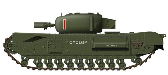
Churchill AVRE
One of the lessons learned during the Dieppe raid in 1942 was
the Canadian engineers were unable to proceed with obstacle
demolitions and beach clearing without sustaining heavy
casualties. A Canadian engineer officer put forward the idea of
using a tank converted for the use of engineers which would
carry them and the demolition charges to the target. The idea
was accepted, and after deliberation the Churchill tank was
selected as the most suitable vehicle for conversion. The
interior was stripped out and the main armament removed,
allowing the storage of specialised demolition equipment and
S P E C I F I C A T I O N :
Vehicle Weight: 38.5 tons
Dimensions: Length 24 ft 5 ins, Width 8 ft, Height 8 ft 2 ins
Powerplant: 1 x Bedford 350 hp petrol engine
Performance: Maximum speed 12½ mph, Range 90 miles
Armament: 1 x 290 mm Spigot Mortar, 1 x 7.62 mm machine gun
Armour: Maximum thickness 102 mm
Crew: 4
the ability to carry a demolition squad. The main turret was
retained, but in place of the main gun a Petard spigot mortar
was fitted which threw a 40 lb ‘Flying dustbin’ bomb a distance
of 150 yards. Known as the Churchill AVRE (Armoured Vehicle
Royal Engineers), they quickly became the standard equipment
used by the engineers attached to formations such as the 79th
Armoured Division and other assault brigades. The Churchill
AVRE was first used on a large scale during the Normandy
landings in June 1944, and proved effective in demolishing
structures such as pillboxes, bunkers and buildings.
Country of Origin: UK
Number Built: 754
S P E C I A L I S E D A R M O U R E D V E H I C L E
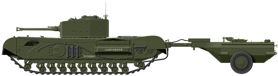
Churchill ‘Crocodile’
After the Petroleum Warfare Department was established in
1940 in response to the invasion scare, a design was prepared
of a projector that used compressed gas to propel a flame jet.
The first Churchill flamethrower tanks were the idea of Major
Oke who positioned the flame projector in the hull machine
gunner's position, and three of thes tanks took part in the
Dieppe Raid in 1942 but could not get off the beach and were
destroyed. Work on the idea was also being carried out by the
Petroleum Warfare Department and AEC who began to use the
Churchill for further development. In 1943 General Percy
S P E C I F I C A T I O N :
Vehicle Weight: 39 tons
Dimensions: Length 25 ft 1 in,Wwidth 8 ft, Height 8 ft 2 ins
Powerplant: 1 x Bedford 350 hp petrol engine
Performance: Maximum speed 12½ mph, Range 90 miles
Armament: 1 x flamethrower (maximum range 120 yds),
1 × 75 mm gun, 1 × 7.62 mm Besa machine gun
Armour: Maximum thickness 152 mm • Crew: 5
Hobart saw a demonstration of the flamethrower tank which
he immediately added to the equipment needed for the 79th
Division. The equipment for the flamethrower was produced as
a kit that REME workshops could fit in the field and convert any
available Churchill Mk VII. The conversion kit consisted of the
trailer, an armoured pipe fitted along the underside of the tank,
and the projector, which replaced the hull mounted Besa
machine gun. This allowed the tank to retain its main gun and
operate as a normal gun tank if necessary. They remained in
service with the British Army until the early 1960s.
Country of Origin: UK
Number Converted: 800
S P E C I A L I S E D A R M O U R E D V E H I C L E
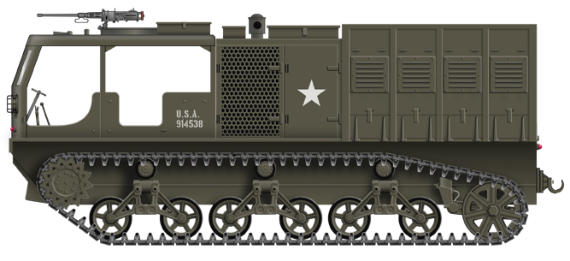
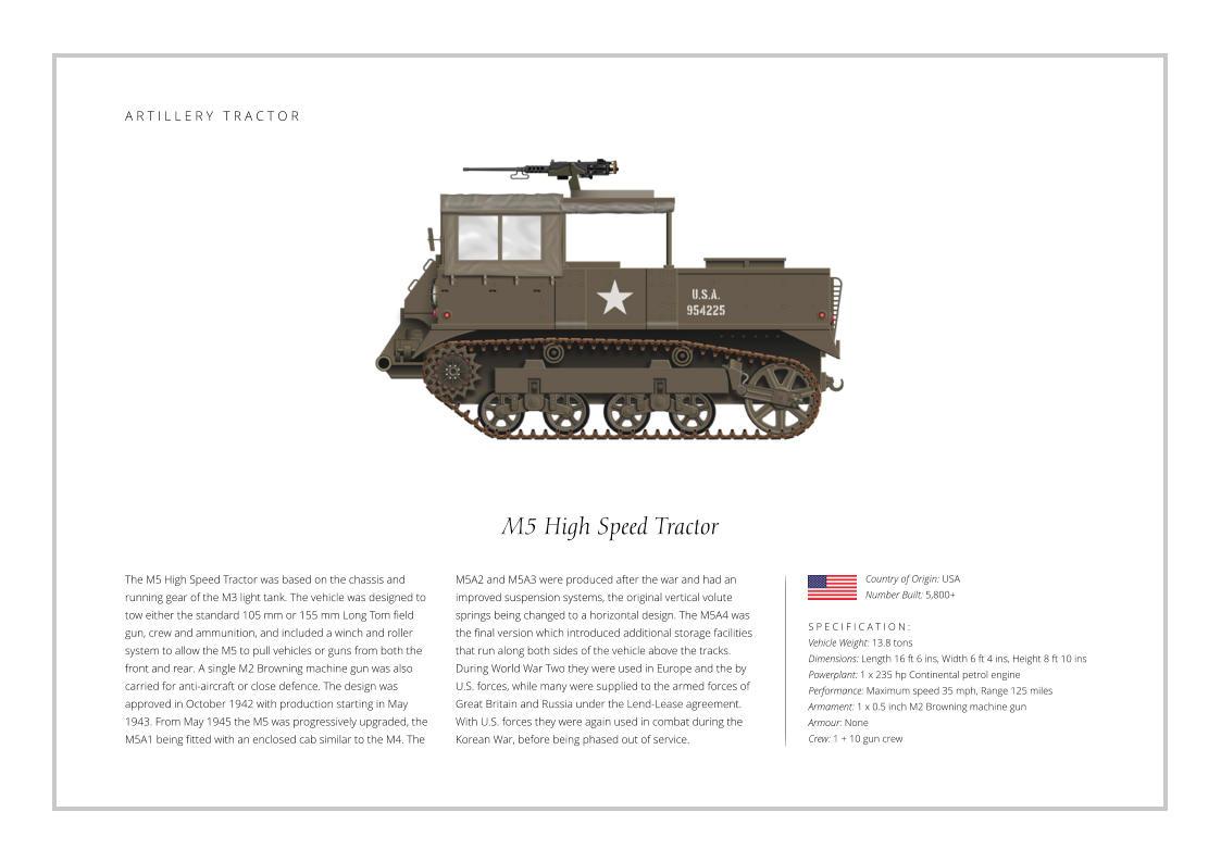
M6 High Speed Tractor
To tow the heavier American 8 inch (203 mm) and 240 mm
howitzers during World War Two, a larger version of the M4
High Speed Tractor was produced. This was the M6 HST which
was longer and wider with two extra running wheels added to
each side with complete with suspension units and powered by
two engines. The M6 began to enter service in 1944, and by the
time production ended in 1945, 1,235 had been built. The M6,
along with the and M4 HST, were mainly deployed in Italy and
North Western Europe by U.S. forces during World War Two.
During the Korean War in the early 1950s only the M4 was
S P E C I F I C A T I O N :
Vehicle Weight: 34.5 tons
Dimensions: Length 21 ft 6 ins, Width 10 ft, Height 8 ft 8 ins
Powerplant: 2 x 190 hp Waukesha petrol engines
Performance: Maximum speed 21 mph, Range 110 miles
Armament: 1 x 0.5 inch M2 Browning machine gun
Armour: None
Crew: 1 + 10 gun crew
deployed by U.S. forces, mainly due to the withdrawal of most
of the heavy artillery. After World War Two and into the 1950s,
many surplus M4 and M6s were supplied to Brazil, Greece,
Holland, Japan, Yugoslavia, Israel and Pakistan under the
Mutual Defence Assistance Programme, while in the U.S. the
last M6 was withdrawn in 1959 and the M4 in 1960, by which
time the decision had been made to adopt more self-propelled
guns. Further surplus vehicles were then sold and converted
for civilian use, where they were primarily used in the logging
and road construction industry.
Country of Origin: USA
Number Built: 1,235
A R T I L L E R Y T R A C T O R
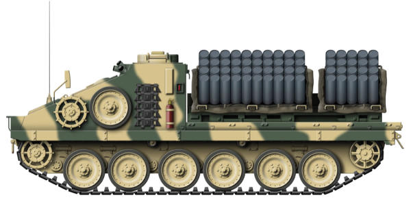
Shielder VLSMS
In the early 1990s the British Army became aware of the need
for a system that could lay a defensive anti-tank mine barrier
quickly. A flatbed version of the Alvis Stormer was chosen as
the delivery vehicle and two systems were trialled, the French
Minotaur Scatterable minelaying system and the American
Volcano mine system, but after trials the U.S. Vocano system
was chosen. The system consist of up to 40 dispensers that
contain 6 mines each which are mounted on the flatbed. The
mines are launched to the sides and rear of the vehicle as it
moves across the terrain, quickly creating a mine barrier. Each
S P E C I F I C A T I O N :
Weight: 10 tons
Dimensions: Length 17 ft 4 ins, Width 7 ft 10 ins, Height 7 ft 3 ins
Powerplant: 1 x Perkins 250 hp diesel engine
Performance: Maximum speed 50 mph, Range 400 miles
Armament: 40 mine dispensers and 240 mines
Armour: Not available
Crew: 2
mine has a programmable life of 4 hours, 48 hours or 15 days,
after which they self-destruct, a control unit providing the fire
signals, testing and arming of the self-destruct mechanism. The
new weapons system was named Shielder VLSMS and was
ordered in 1995, the first units being deployed in 1999. It is
reported that twenty-nine Shielder systems were in service with
the British Army in 2009, but were removed from active service
during 1913/14. Other roles for the Alvis Stormer include an
ambulance, air defence, recovery, and as a command vehicle,
along with its original role of an armoured personnel carrier.
Country of Origin: UK
Number Produced: 30+
S P E C I A L I S E D A R M O U R E D V E H I C L E
Landwirtschaftlicher Schlepper (LaS)
After the National Socialists came to power in Germany during
1933, their first priority was to expand and rearm the army
after the limitations imposed on the country by the Treaty of
Versaille in 1919. The Panzer I can be traced back to 1932 and
the Landwirtschaftlicher Schlepper (LaS), which was classified
as an agricultural tractor. The LaS was the Panzer I without any
super-structure or turret, the interior being open with seating
to carry troops or supplies. 15 were built by five different
companies in order for them to gain knowledge in tank
construction, the vehicles then being used to train German
S P E C I F I C A T I O N :
Vehicle Weight: 3.5 tons
Dimensions: Length 13 ft 2 ins, Width 6 ft 8 ins, Height 5 ft 6 ins
Powerplant: 1 x Krupp M 305 59 hp petrol engine
Performance: Maximum speed 23 mph, Range 90 miles
Armament: None
Armour: Maximum thickness 13 mm
Crew: 2
Panzer troops in the use of tracked vehicles. By the end of
1941 the Panzer I Ausf A had been withdrawn from service and
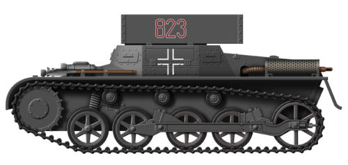
converted for other uses. One of the many conversions carried
out on the Panzer I was the Munitionsschlepper (ammunition
tractor). These had the turret removed and the aperture fitted
with a two piece armoured cover plate, to load and access the
ammunition which was carried inside. Later an armoured box
was fitted on top of the vehicle which allowed for easier and
quicker transfer of shells. These vehicles served with regular
Panzer formations during the Polish and French campaigns.
Country of Origin: Germany
Number Produced: 15
S P E C I A L I S E D A R M O U R E D V E H I C L E


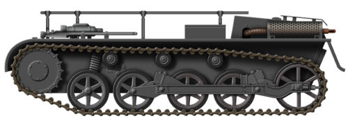
Munitionsschlepper Ausf A
After the National Socialists came to power in Germany during
1933, their first priority was to expand and rearm the army
after the limitations imposed on the country by the Treaty of
Versaille in 1919. The Panzer I can be traced back to 1932 and
the Landwirtschaftlicher Schlepper (LaS), which was classified
as an agricultural tractor. The LaS was the Panzer I without any
super-structure or turret, the interior being open with seating
to carry troops or supplies. 15 were built by five different
companies in order for them to gain knowledge in tank
construction, the vehicles then being used to train German
S P E C I F I C A T I O N :
Vehicle Weight: 5 tons
Dimensions: Length 13 ft 2 ins, Width 6 ft 8 ins, Height 5 ft 6 ins
Powerplant: 1 x Krupp M 305 59 hp petrol engine
Performance: Maximum speed 23 mph, Range 90 miles
Armament: None
Armour: Maximum thickness 13 mm
Crew: 2
Panzer troops in the use of tracked vehicles. By the end of
1941 the Panzer I Ausf A had been withdrawn from service and
converted for other uses. One of the many conversions carried
out on the Panzer I was the Munitions-schlepper (ammunition
tractor). These had the turret removed and the aperture fitted
with a two piece armoured cover plate, to load and access the
ammunition which was carried inside. Later an armoured box
was fitted on top of the vehicle which allowed for easier and
quicker transfer of shells. These vehicles served with regular
Panzer formations during the Polish and French campaigns.
Country of Origin: Germany
Number Produced: 51
S P E C I A L I S E D A R M O U R E D V E H I C L E
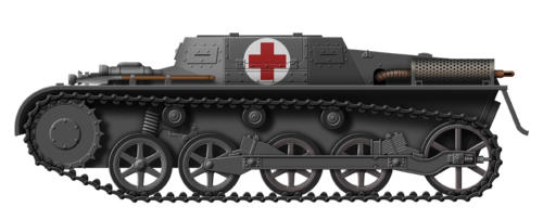
Krankenpanzerwagen Ausf A
After the National Socialists came to power in Germany during
1933, their first priority was to expand and rearm the army
after the limitations imposed on the country by the Treaty of
Versaille in 1919. The Panzer I can be traced back to 1932 and
the Landwirtschaftlicher Schlepper (LaS), which was classified
as an agricultural tractor. The LaS was the Panzer I without any
super-structure or turret, the interior being open with seating
to carry troops or supplies. 15 were built by five different
companies in order for them to gain knowledge in tank
construction, the vehicles then being used to train German
S P E C I F I C A T I O N :
Vehicle Weight: 4.7 tons
Dimensions: Length 13 ft 2 ins, Width 6 ft 8 ins, Height 5 ft 6 ins
Powerplant: 1 x Krupp M 305 59 hp petrol engine
Performance: Maximum speed 23 mph, Range 90 miles
Armament: None
Armour: Maximum thickness 13 mm
Crew: 2
Panzer troops in the use of tracked vehicles. By the end of
1941 the Panzer I Ausf A had been withdrawn from service and
converted for other uses. One of the many conversions carried
out on the Panzer I was the Munitions-schlepper (ammunition
tractor). These had the turret removed and the aperture fitted
with a two piece armoured cover plate, to load and access the
ammunition which was carried inside. Later an armoured box
was fitted on top of the vehicle which allowed for easier and
quicker transfer of shells. These vehicles served with regular
Panzer formations during the Polish and French campaigns.
Country of Origin: Germany
Number Produced: Unknown
S P E C I A L I S E D A R M O U R E D V E H I C L E
S P E C I A L I S E D A R M O U R E D V E H I C L E
S P E C I A L I S E D A R M O U R E D V E H I C L E
S P E C I A L I S E D A R M O U R E D V E H I C L E
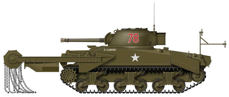
Sherman ‘Crab’
The American M4 Sherman was used for a variety of roles
during World War Two, especially by the British who developed
several types specifically for the D-Day landings in 1944.
Various ideas clearing a path through a minefield had been
investigated, but the idea of using chain flails to detonate
mines ahead of a tank had been proven in North Africa during
1942 with the Matilda ‘Scorpion’. Development continued and a
new device followed which was known as the Crab. The Crab
had 43 chains mounted on a drum that was powered by the
main engine, while screens were fitted to shield the front of the
S P E C I F I C A T I O N :
Vehicle Weight: 33.9 tons
Dimensions: Length 24 ft 8 ins, Width 8 ft 9½ ins, Height 11 ft 3 ins
Powerplant: 1 x Chrysler 445 hp petrol engine
Performance: Maximum speed 20 mph, Range 100 miles
Armament: 1 x 75 mm gun, 1x 0.5 inch, 2 x 0.3 inch machine guns
Armour: Maximum thickness 50 mm
Crew: 5
tank from flying dust and debris, and later a device allowed the
flails to follow contours of the ground. The Crab was usually
fitted to a Sherman tank and unlike the Matilda ‘Scorpion’, the
Sherman ‘Crab’ was a more effective as it retained its turret
and main gun so they could fight if required. The Sherman
‘Crab’ was first used in action by the British 79th Armoured
Division before the U.S. Army received their initial examples,
with the type becoming the most widely used mine flail tank of
World War Two, and were deployed during the Allied advances
of 1944-1945 in Western Europe.
Country of Origin: UK
Number Produced: Unknown
DD Sherman
In 1941 Britain began to develop an amphibious tank which
utilised a collapsible fabric screen. This contained rubber air
tubes, which when inflated raised the screen and locked in
position. The tank could then be driven into the water and
would float with about 3 ft of freeboard, drive being provided
by two screw propellers. Trials were carried out using the
Tetrarch and Valentine tank, although the water speed low and
any sea state over 5 was risky. In 1943 the M4 was chosen for
conversion, and when waterproofed and fitted with the system
were known as the DD (Duplex Drive) Sherman. On D-Day they
S P E C I F I C A T I O N :
Vehicle Weight: 32.7 tons
Dimensions: Length 24 ft 8 ins, Width 8 ft 9½ ins, Height 11 ft 3 ins
Powerplant: 1 x Ford 450 hp petrol engine
Performance: Maximum speed 29 mph, 4 knots in water
Armament: 1 x 75 mm gun, 2 x 0.3 inch machine guns
Armour: Maximum thickness 62 mm
Crew: 5
proved an asset for the British, although a number were lost by
being swamped. Once they neared the beach the screen could
be collapsed and the main armament could be engaged,
providing valuable fire support for the troops on the beaches.
Another vehicle was the Sherman BARV (Beach Armoured
Recovery Vehicle). This was designed to remove vehicles that
became stranded in the surf, blocking access to the beaches.
The tank was waterproofed and the turret replaced by a tall
armoured superstructure. They were able to operate in 9 feet
of water and first used during D-Day landings in 1944.
Country of Origin: UK
Number Produced: Unknown

S P E C I A L I S E D A R M O U R E D V E H I C L E
S P E C I A L I S E D A R M O U R E D V E H I C L E
Sherman BARV
The Sherman BARV (Beach Armoured Recovery Vehicle) was
was designed by the REME (Royal Electrical and Mechanical
Engineers) to remove vehicles that became stranded in the
water and blocked access to the beaches during amphibious
landings. The tank was waterproofed and the turret replaced
by a tall armoured superstructure. They were operated by a
crew of 5 or 6 and able to operate in 9 feet of water. They were
first used during the D-Day landings in June 1944, followed by
the landings in the south of France in August. In the 1950s the
Centurion BARV was produced, which has now been replaced
S P E C I F I C A T I O N :
Vehicle Weight: 30.3 tons
Dimensions: Length 19 ft 2 ins, Width 8 ft 7 ins, Height 9 ft
Powerplant: 1 x General Motors 375 hp petrol engine
Performance: Maximum speed 30 mph, Range 100 miles
Armament: None
Armour: Maximum thickness 62 mm
Crew: 5/6
by the Hippo BARV. Another vehicle was DD Sherman which
was an amphibious tank that utilised a collapsible fabric screen.
This contained rubber air tubes, which when inflated raised the
screen and locked in position. The tank could then be driven
into the water and would float with about 3 ft of freeboard,
drive being provided by two screw propellers. On D-Day they
proved an asset for the British, although a number were lost by
being swamped. Once they neared the beach the screen could
be collapsed and the main armament could be engaged,
providing valuable fire support for the troops on the beaches.
Country of Origin: UK
Number Produced: 60+
S P E C I A L I S E D A R M O U R E D V E H I C L E


Pages


